Objective
-
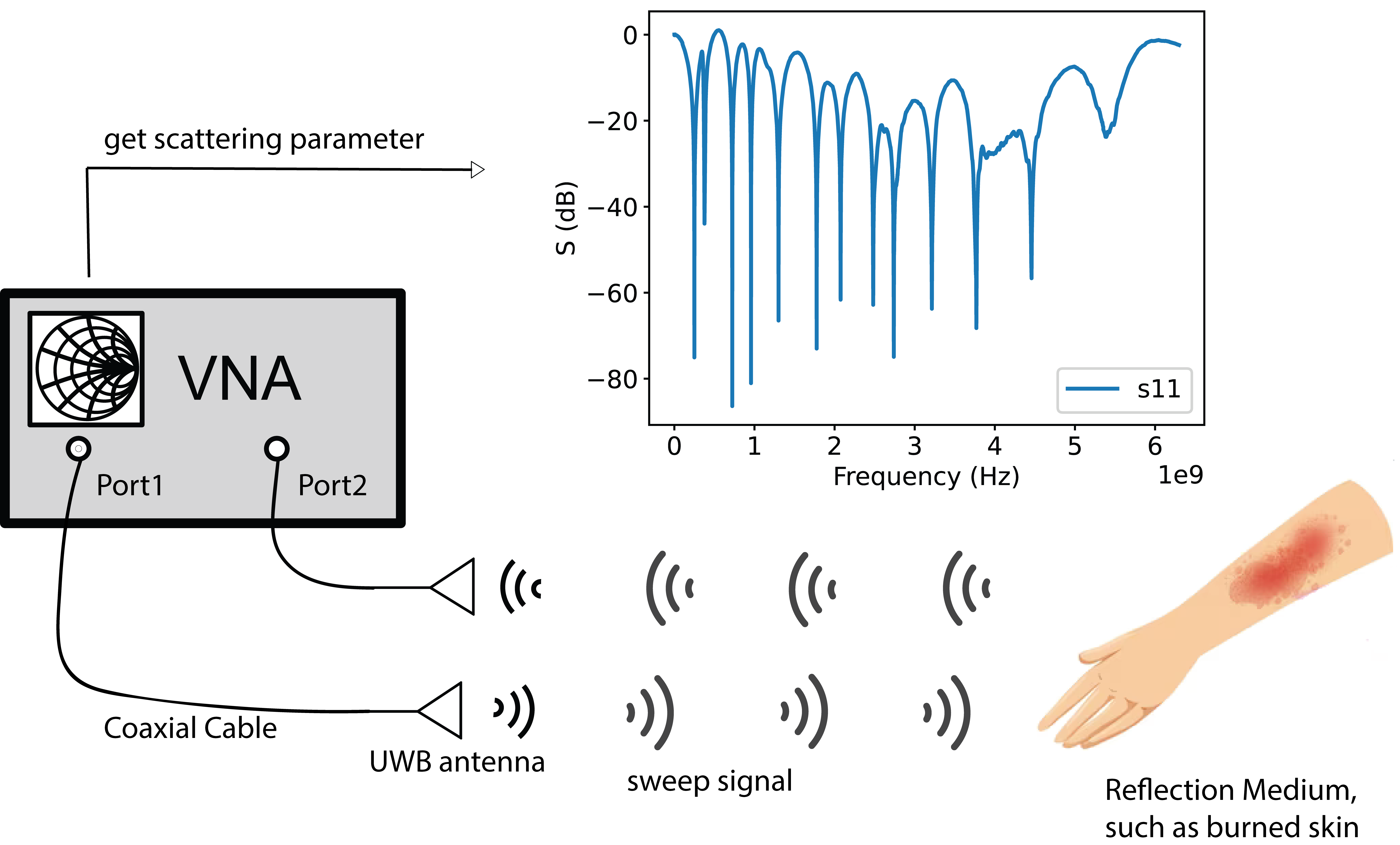
A VNA based experiment setup is constructed for mimicking UWB apparatus.
-
Produce UWB signals by synthesizing waveforms with various frequencies.
-
Validate the setup and UWB signal transmitting/receiving processes by testing the distance among the system and a moving metal obstacle.
Hypothesis
It is assumed that wave reflecting procedure is linear
Materials
- VNA device, KEYSIGHT 5063A ENA
- N Male to SMA Female Connector
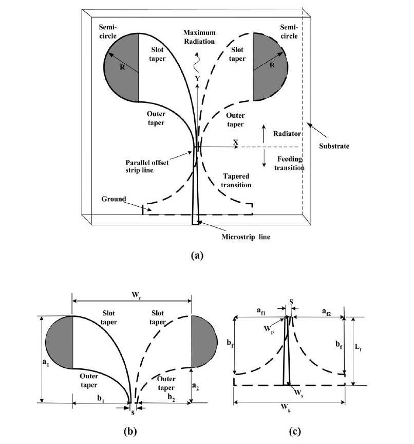
- UWB antenna, provided by Gary (Shenzhen), bandwidth 3 - 20GHz
- Metal plate, as a wave full reflection obstacle, size 34cm
Method
Setup Diagram

| Option | Value |
|---|---|
| RF Power | -5dBm |
| IF Bandwidth | 70kHz |
| Averaging | 64 |
| Start Frequency | 100kHz |
| Stop Frequency | 6.5GHz |
| Number of Frequency Points | 10001 |
UWB Signal Generation
The present VNA device only can eject sweeping signals, with frequency range 100kHz - 6.5GHz. How to produce UWB signal is the key problem in the experiment.
The key assumption of the experiment is that the signal is transmitted from the VNA Port1 port and received at Port2, and the whole process is linear. Thus,
That is, a UWB signal can be represented by a linear superposition of the swept signals with varying frequency, and at the receiving port, by summing the returned signals responding to the swept emitting waves one can get the full reflected UWB signal.
We can follow the spectrogram of the Gaussian pulse modulated by the cosine signal to adjust the intensity of the signals of different frequencies of our sweep signal, and then get the Gaussian pulse modulated by the cosine signal by summing up these signals, and the following is the mathematical formula analysis and the resultant figure
Gaussian Impulse Signal modulated by the cosine signal:
where the center frequency is the frequency of the cosine signal and the bandwidth of the pulse is controlled by the parameter of the Gaussian signal.
By following two Fourier transform pairs we can obtain the spectrogram of a Gaussian pulse,
So, spectrum of cosine signal modulation gaussian pulse:
Here’s the result,
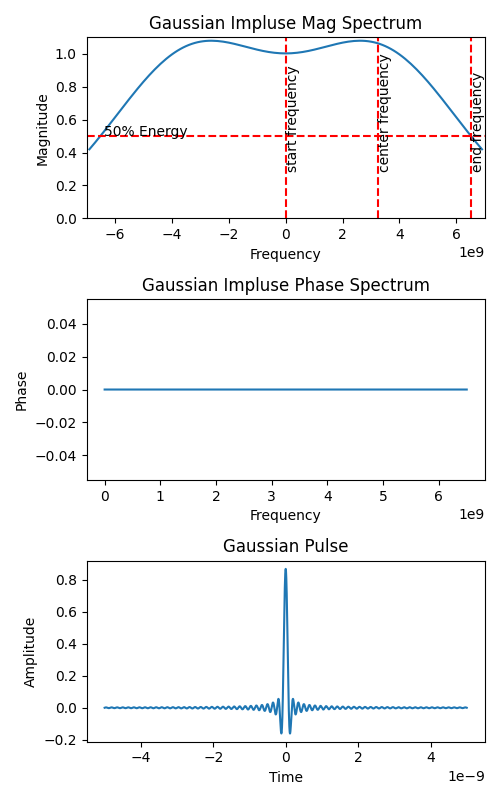
The two diagrams above are the magnitude spectrum and phase spectrum derived from the Fourier transform of a Gaussian pulse signal modulated by a cosine signal. In generating Gaussian pulses, we consider the spectrogram energy drop to 50% as the termination of the bandwidth. We can get a Gaussian pulse by summing the frequencies we have adjusted according to the above magnitude spectrum and phase spectrum. Under the assumption of a linear system, the swept signal that is emitted can be emitted by us as a Gaussian pulse, and the emitted signal looks as shown in the figure.
Scattering Parameters
is defined as the square root of the ratio of the energy reflected from the Port1 port to the input energy, and is often simplified as the ratio of the equivalent reflected voltage to the equivalent incident voltage.
represents the insertion loss, that is, how much energy has been transmitted to the destination (Port2), the larger the value, the better, the ideal value is 1, i.e., 0 dB, the larger the S21 the more efficient the transmission, it is generally recommended that the >0.7, i.e., -3 dB, is considered to have occurred the signal transmission.
Time-domain Signal Construction by Scattering Parameters
We can compute the time-domain signal from the scattering parameters, where the transmitted signal can be obtained from the S11 parameter and the received signal from the S21 parameter.
Also, when we don’t set any reflection material in front of the VNA, there are still parameter which we called initial parameter, which represents the base energy we can get from the port2. When we calculate the receive signal, we need to minus the base energy and because we adjust deferent frequencies signal’s magnitude to fit gaussian pulse, considering these two factors, here’s the adjusted formula we calculate the receive signal,
Procedure
- Start the VNA device.
- Set up the VNA measurement parameters.
- Set the metal plate at different distances from VNA, which are 5cm,10cm,15cm,20cm,25cm,30cm and , which means no reflection.
- Get S11 and S21 scattering parameter from the metal plate at different distances from VNA.
- Analyze raw data - scattering parameter.
Results
Scattering Parameters - S11, S21
First we focus on the raw data we obtained, the scattering parameters, and cause we emit the adjusted magnitude signal to generate gaussian impulse, we also adjust our S21 parameter to match the adjustments of our launch.
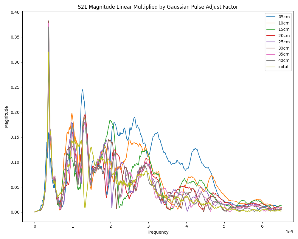
Also, we will minus the base energy we can get from port2 by minus the , here’s the result,
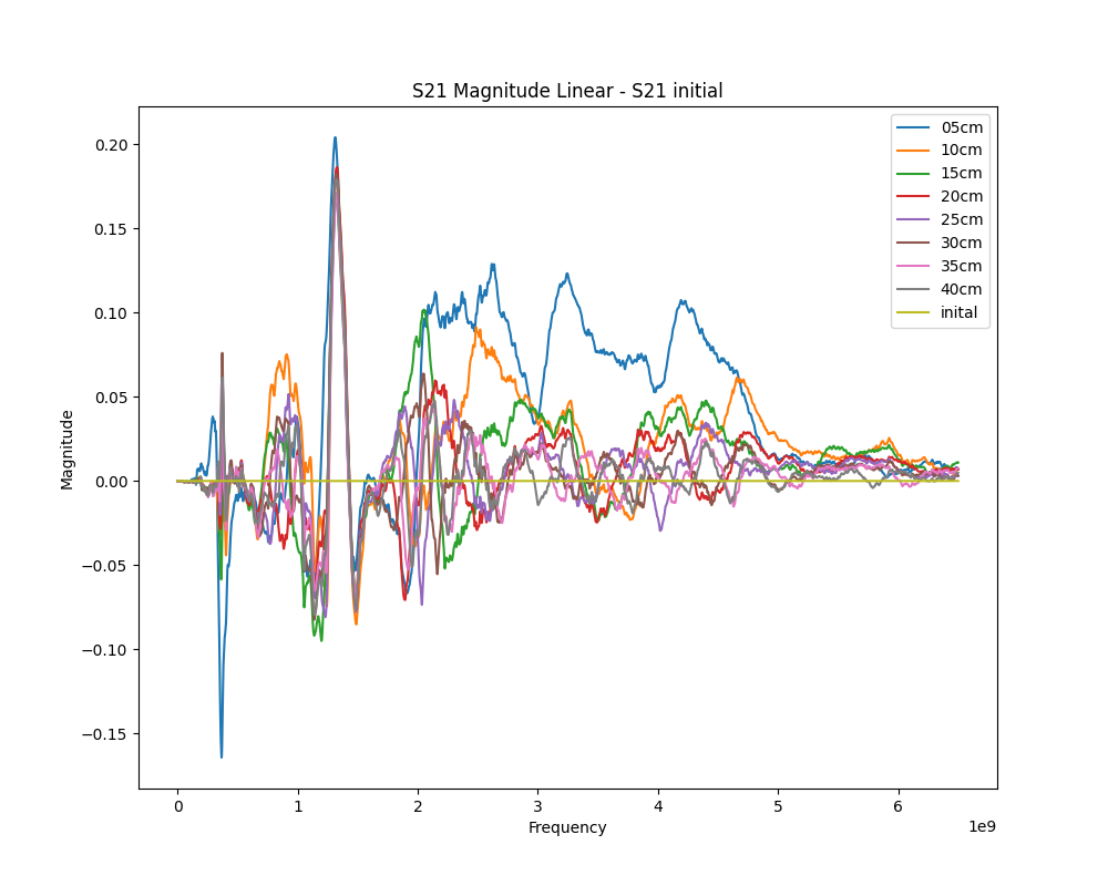
Energy receiving graph for different distance
Refer to Fig 6, the area under S21 curves for estimating the energy received at Port2, as illustrated in Fig 7. The values are given in Table 2.
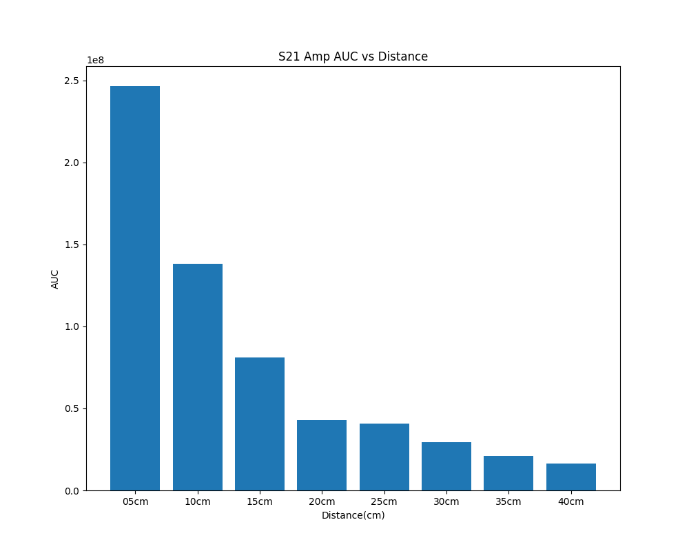
| Distance | AUC |
|---|---|
| 5cm | 1 |
| 10cm | 0.56055976 |
| 15cm | 0.32978441 |
| 20cm | 0.17302525 |
| 25cm | 0.16454077 |
| 30cm | 0.11857247 |
| 35cm | 0.08575671 |
| 40cm | 0.06632118 |
We then used the data from this table to perform polynomial fitting using a grid search method with the MSE (mean squared error) metric as a criterion, as well as five-fold cross-validation, and finally obtained the best result for polynomial fitting as shown below:
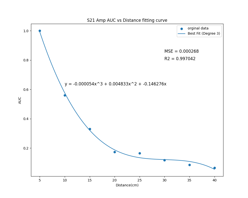
The best fitting function is,
We can get distance from this curve function by solving this cubic equation. The fitting assessment result is and
Receiving Signal Observation

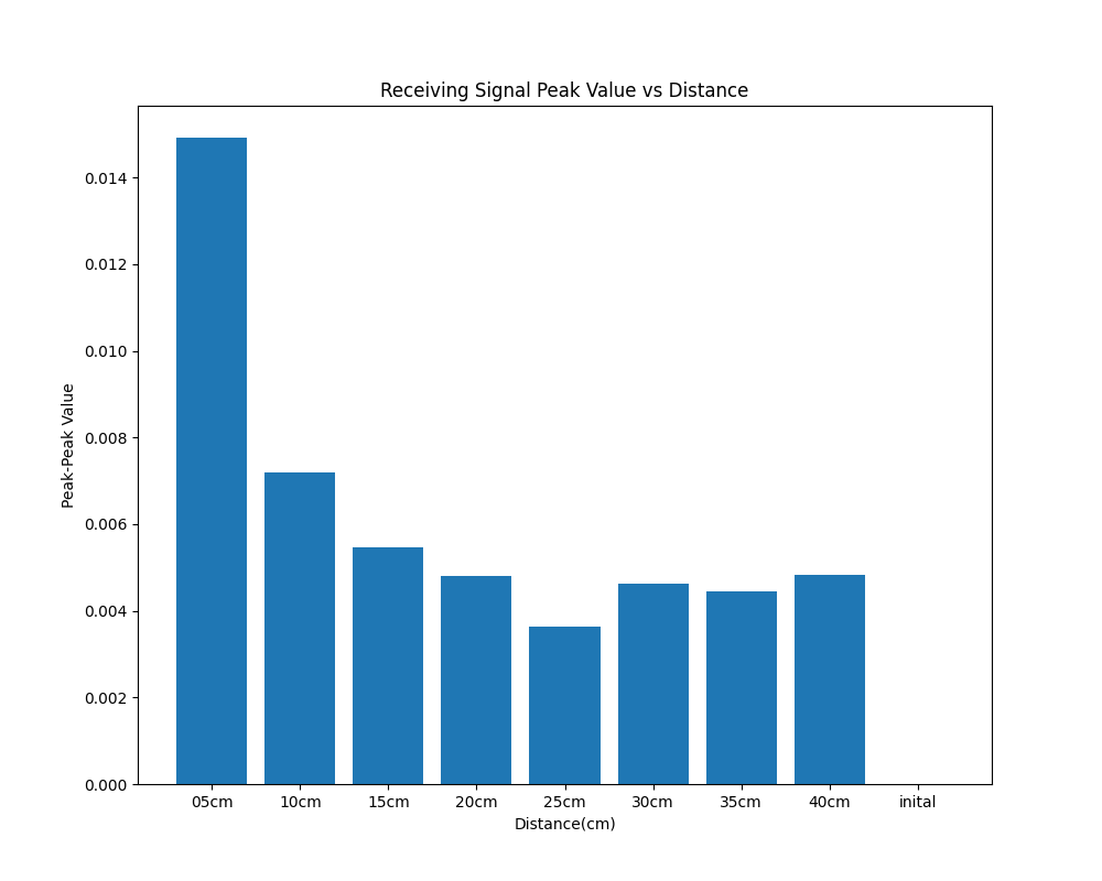
With the S21 parameter and the previously calculated factor, we finally calculate that the signal received by port2, at a minimum frequency of 100kHZ for one cycle. We can get this signals ,
Conclusion and Problem
Conclusion
- Echo UWB signal is capable of range detecting
- By estimating the energy of received signal, the system is able to identify the distance of the metal obstacle ranging 5cm-40cm.
- In accordance with the third degree polynomial law, the energy of the received echo signal decays rapidly within 20 cm, and then the energy decay tends to level off.
Problem
- Is the present simulation protocol of emitting/receiving UWB signal reasonable? Are there optimum method for UWB signal simulation?
- The lack of feed-forward circuitry in VNAs, compared to mature UWB signal transmitting devices, has a significant impact on the strength of both the emitted and received. As a result, the S21 value in Fig 6 is only about 0.35, far below 0.70.