Objective
- Measurement for building a safe experimental environment.
- Reproduced to build the experimental environment and determine the MUTUAL coupling signal in the experimental environment.
- Comparison of the reflective properties of wood and metal materials.
- Construction of time-of-flight calculations in UWB reflection signals under VNA-based systems.
Materials
- VNA device, KEYSIGHT 5063A ENA
- N Male to SMA Female Connector
- Coaxial Cable
- UWB antenna, provided by Gary (Shenzhen), bandwidth 3 - 20GHz
- Metal plate, as a wave full reflection obstacle, size 34cm
- Wood plate,
| Option | Value |
|---|---|
| RF Power | -5dBm |
| IF Bandwidth | 70kHz |
| Averaging | 64 |
| Start Frequency | 100kHz |
| Stop Frequency | 6.5GHz |
| Number of Frequency Points | 10001 |
| Parameter | Value |
|---|---|
| Type | SS405 |
| Length | 30cm |
| Impedance | 50 Ohm |
| Capacitance | 96 pF/m |
| Shielding Effectiveness | 110 dB |
Method
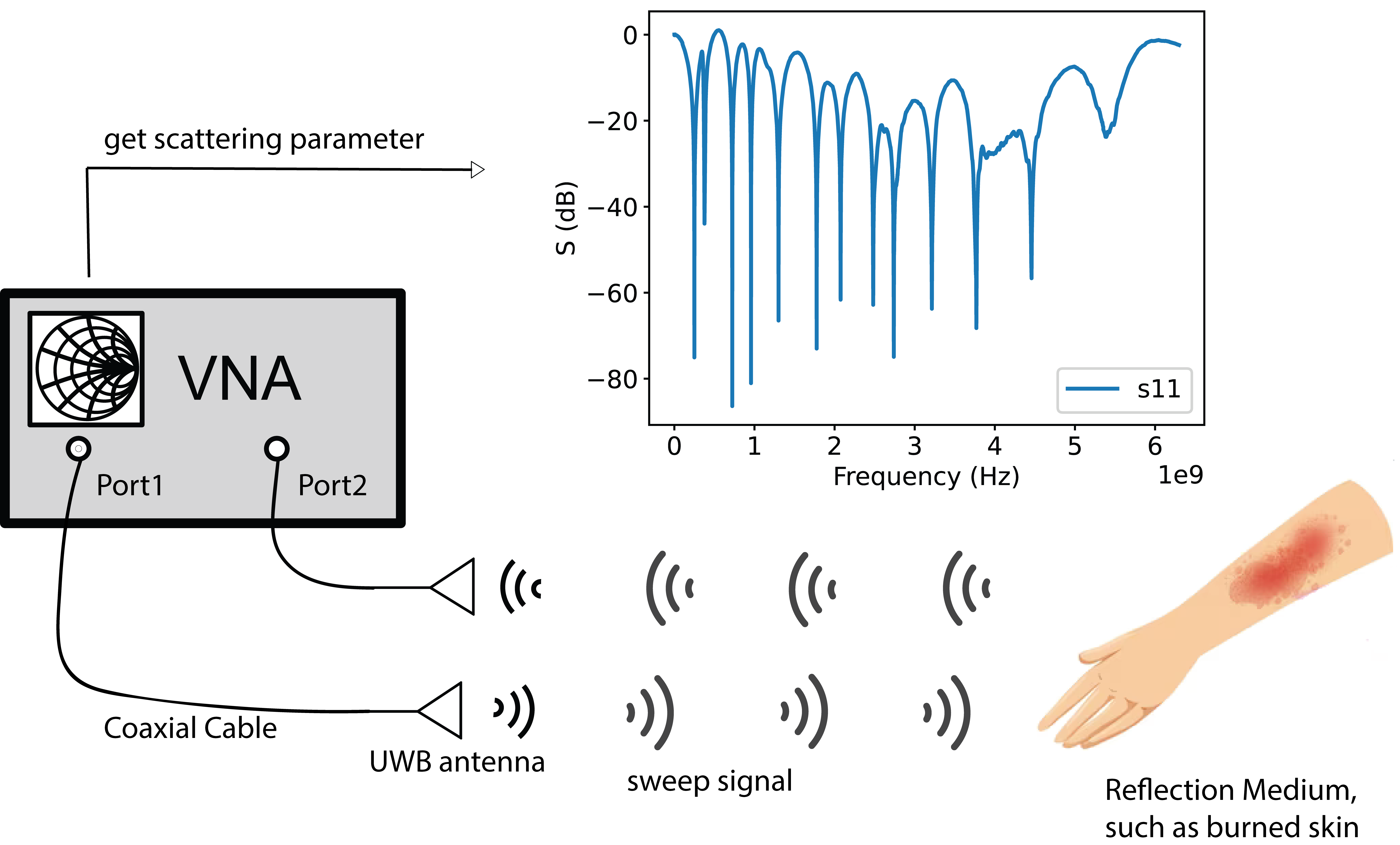
Setup Diagram

Mutual Coupling Signal
Mutual coupling signal refers to the phenomenon where electromagnetic fields from one circuit or antenna influence the behavior of another nearby circuit or antenna. It occurs when the electromagnetic fields generated by one element couple or interact with the other elements in the vicinity.
To get the mutual coupling signal, fix the antennas in a fixed position with a spacing of 8 cm (it can also vary), make sure no object is nearby, and measure the S21 signals. Convert it to a time signal called mutual coupling signal (Sa(t)).
Procedure
- Start the VNA device.
- Set up the VNA measurement parameters.
- Connect antenna to the coaxial cable.
- Measure the mutual coupling signal based on the methods mentioned above.
- Set the wood plate at different distances from VNA, 5cm - 25cm.
- Get S11 and S21 scattering parameter from the wood plate at different distances from VNA.
- Analyze raw data and compare the data with metal plate reflection signal data from experiment 1.