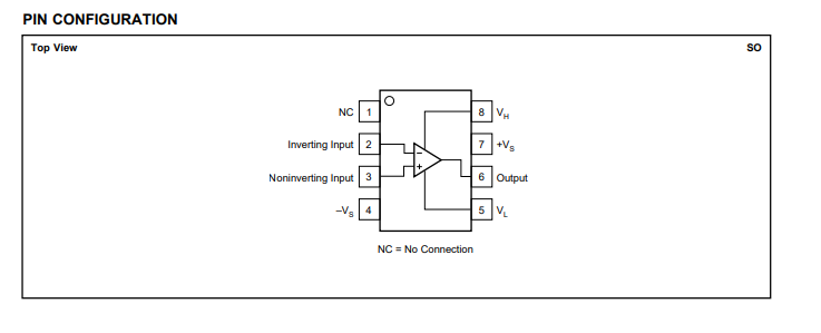
OPA699 Pin Configuration
Board Realistic Diagram
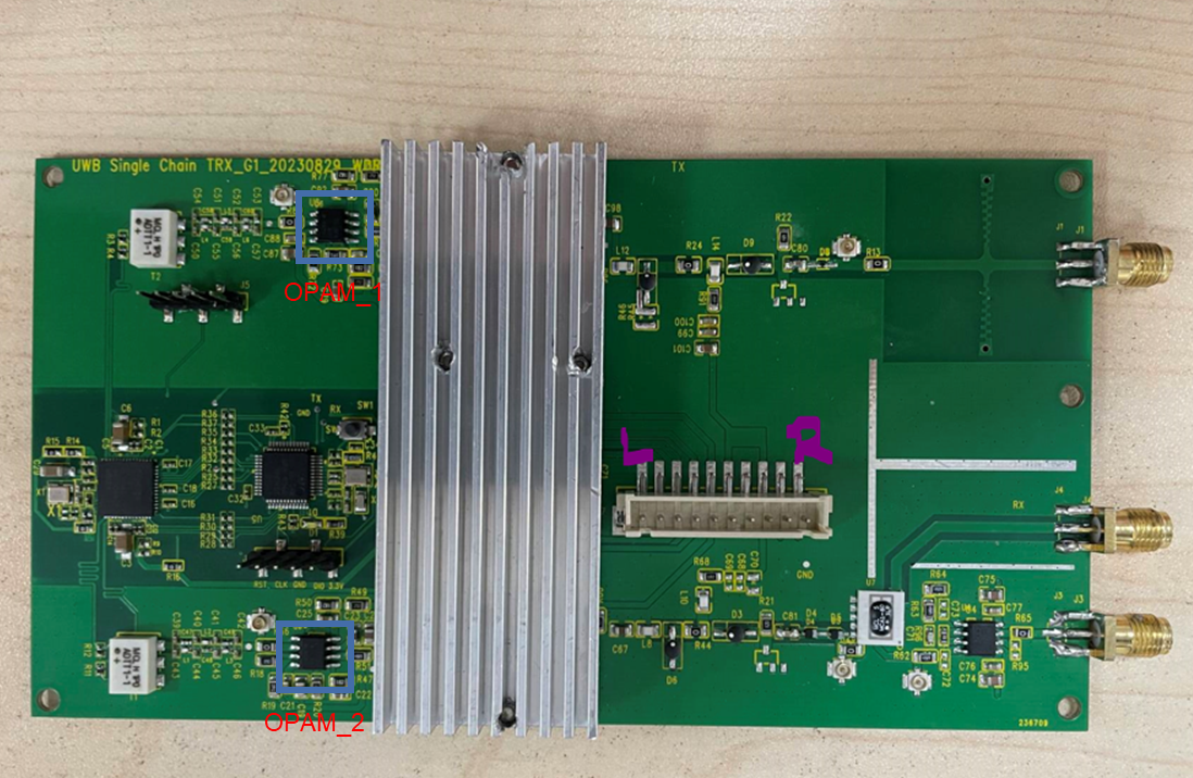
We call OPAM above as OPAM_1, OPAM below as OPAM_2
Test Method
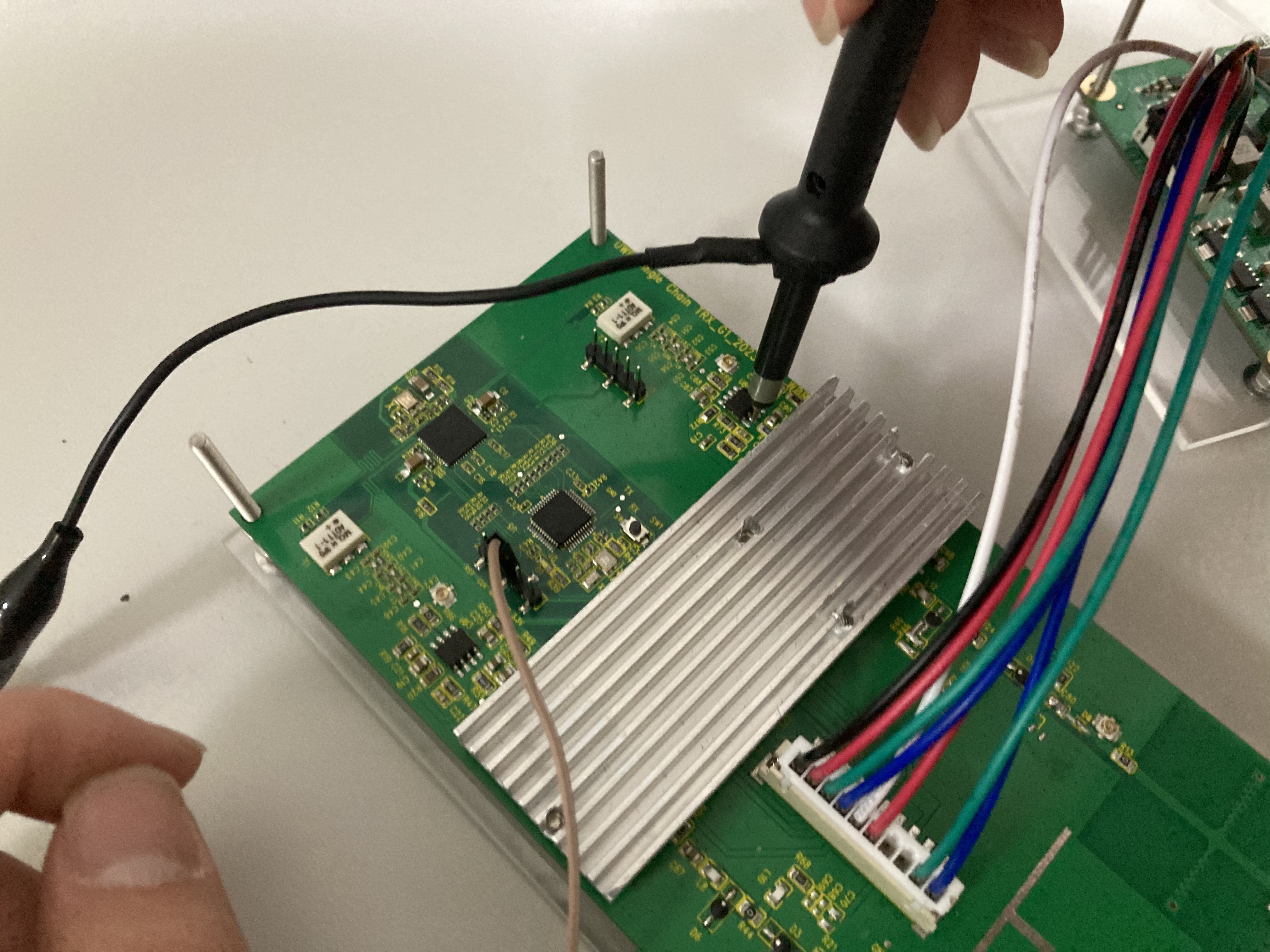
- Connect oscilloscope to inverting input pin and noninverting input pin.
- Connect oscilloscope to Gnd and inverting input pin.
- Connect oscilloscope to Gnd and noninverting input pin.
- Connect oscilloscope to Gnd and output pin.
- Connect oscilloscope to Gnd and NC pin.
Results
OPAM_1
Pin 2,3 Differential Input
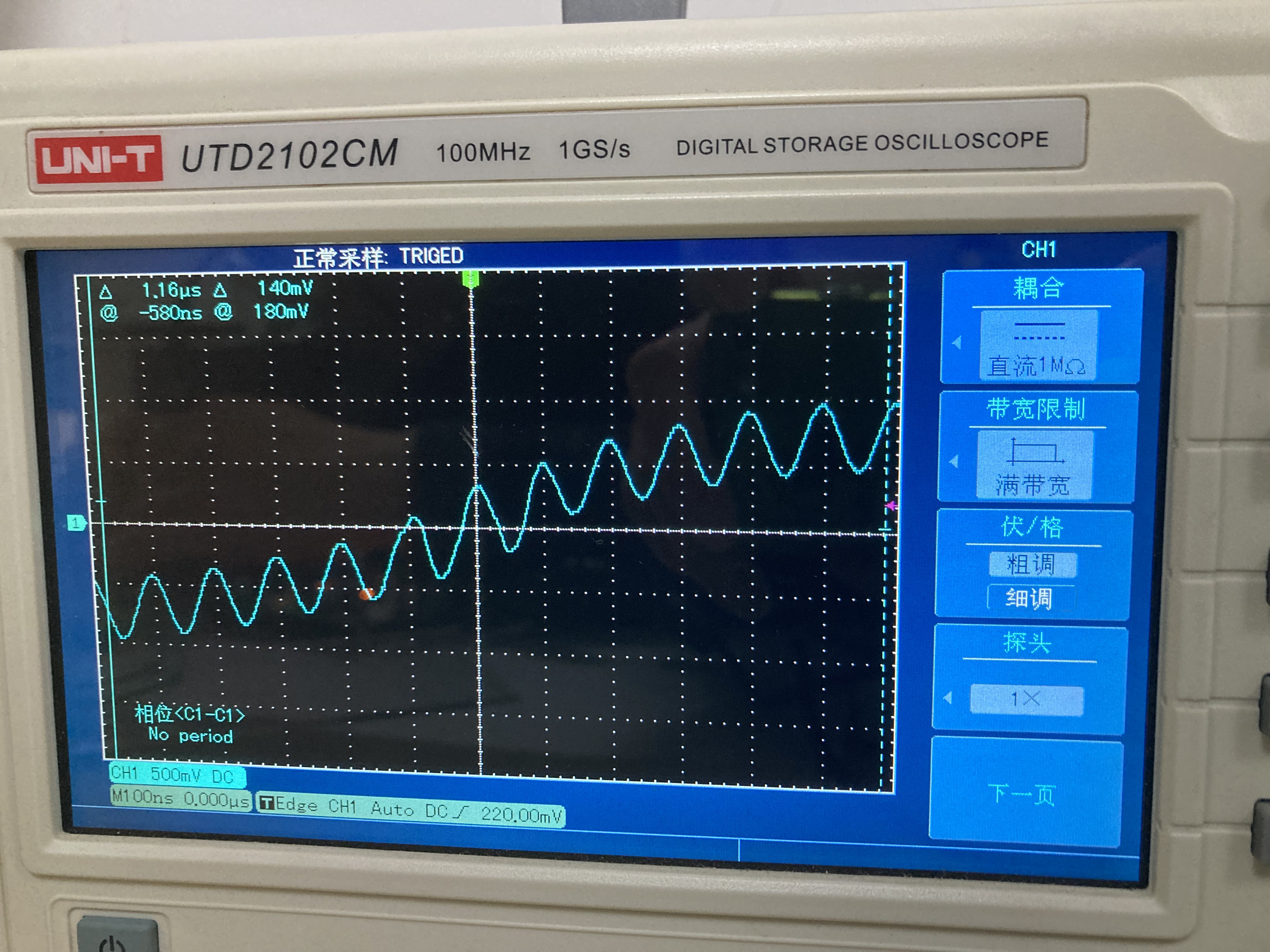
Summary
Peak-Peak Amp ——500mV
Frequency —— 10.00MHz
Pin 2 Inverting Input

Summary
Peak-Peak Amp ——392.0mV
Frequency —— 9.97MHz
Pin 6 - Output
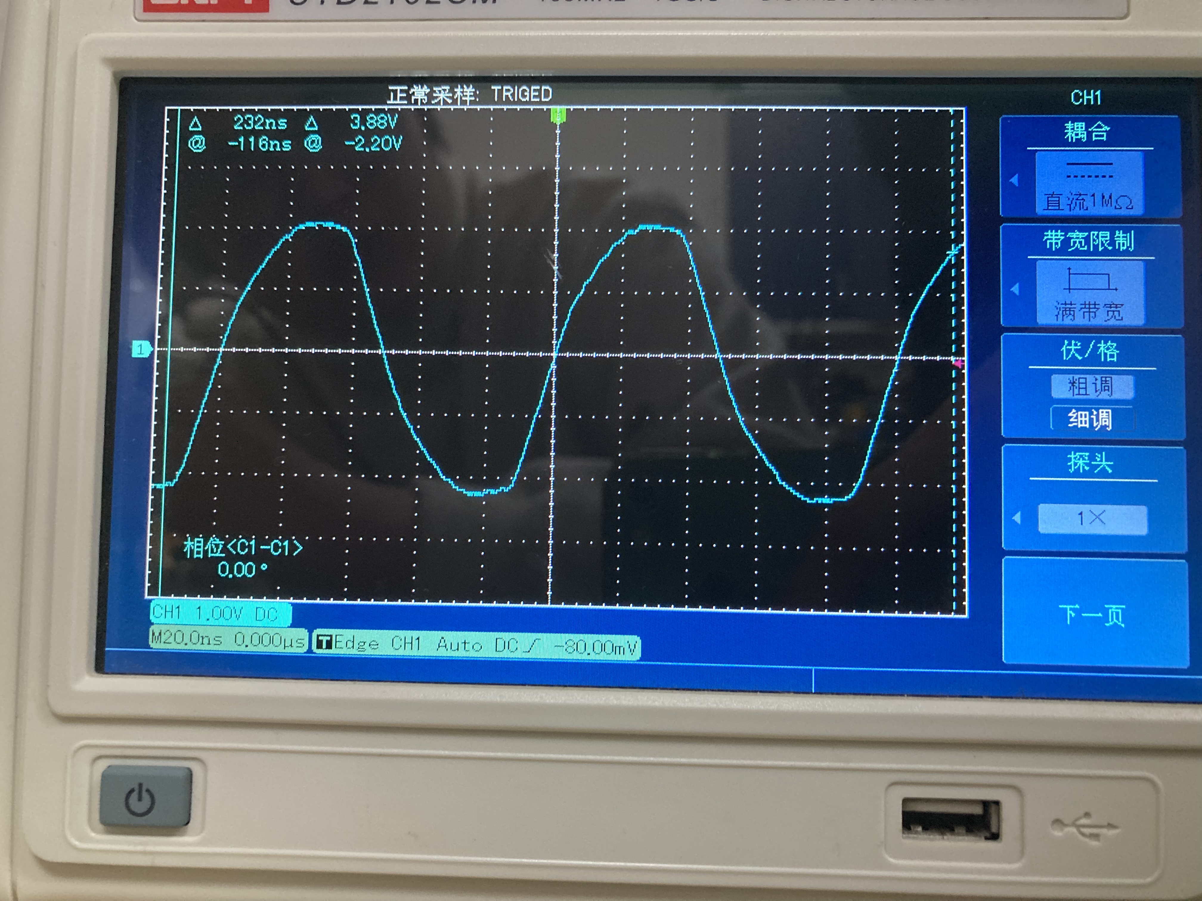
Summary
Peak-Peak Amp —— 4.32v
Frequency —— 10.01MHz
OPAM_2
Pin 2,3 Differential Input
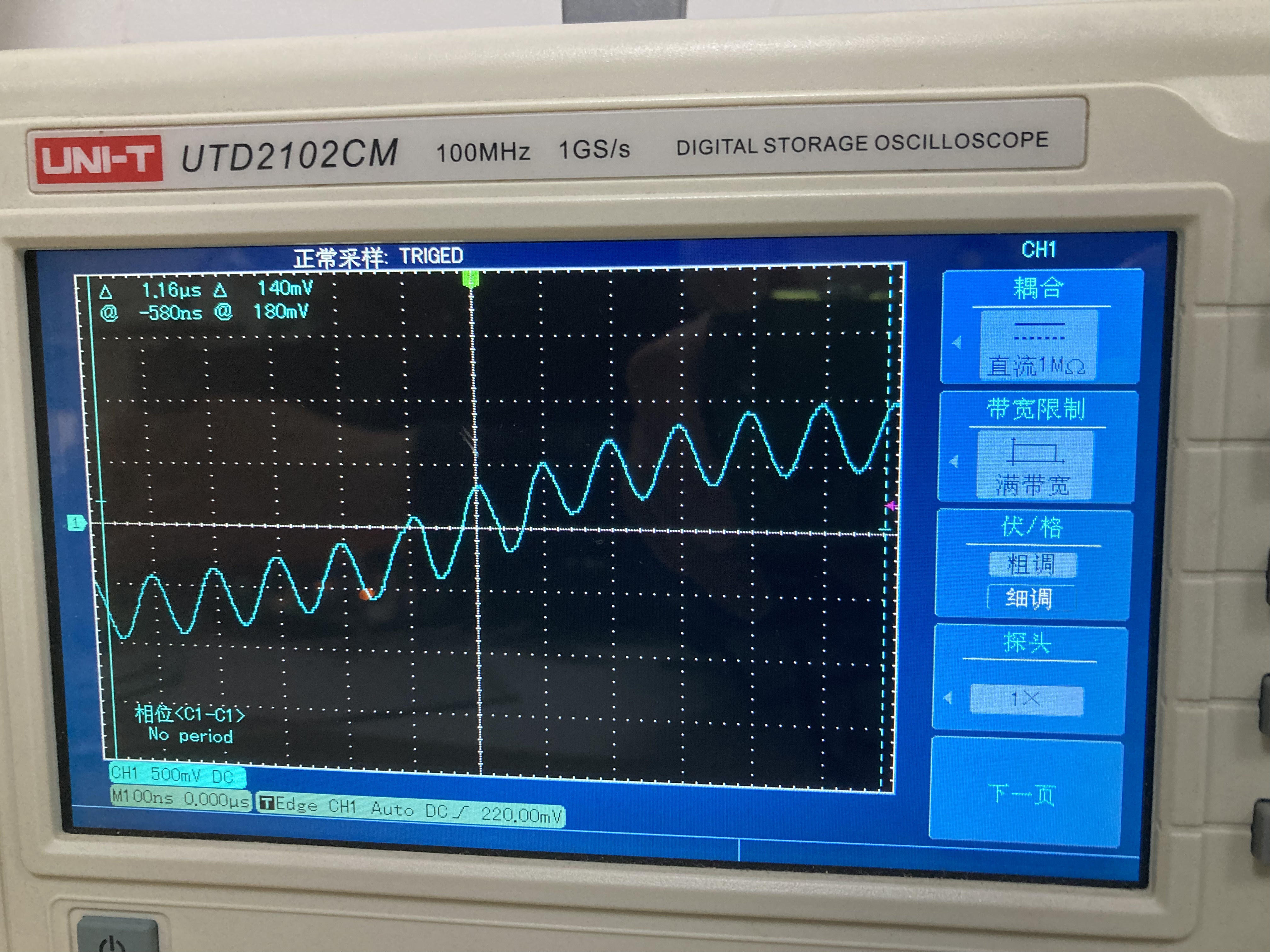
Summary
Peak-Peak Amp ——500mV
Frequency —— 10.00MHz
Pin 2 Inverting Input
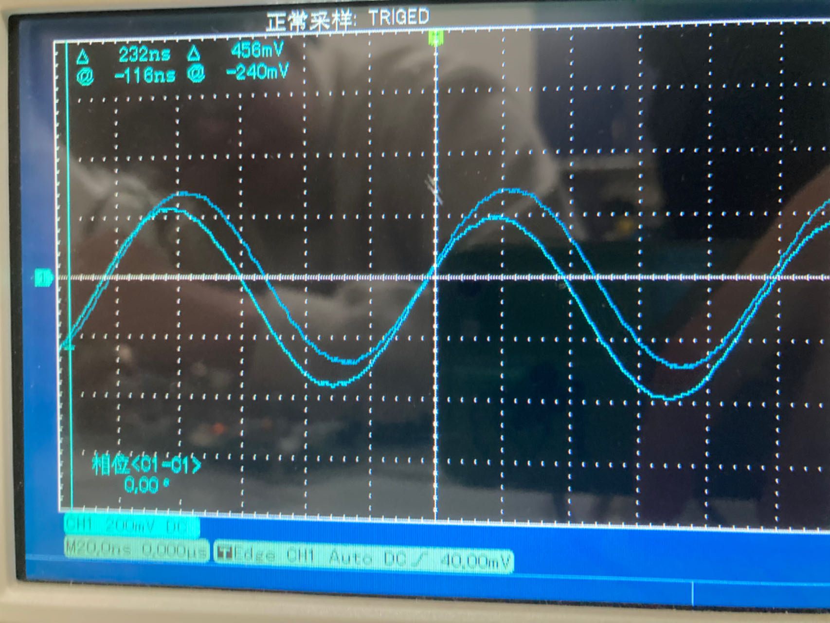
Summary
Peak-Peak Amp ——576.0mV
Frequency —— 10.11MHz
Pin 3 Noninverting Input
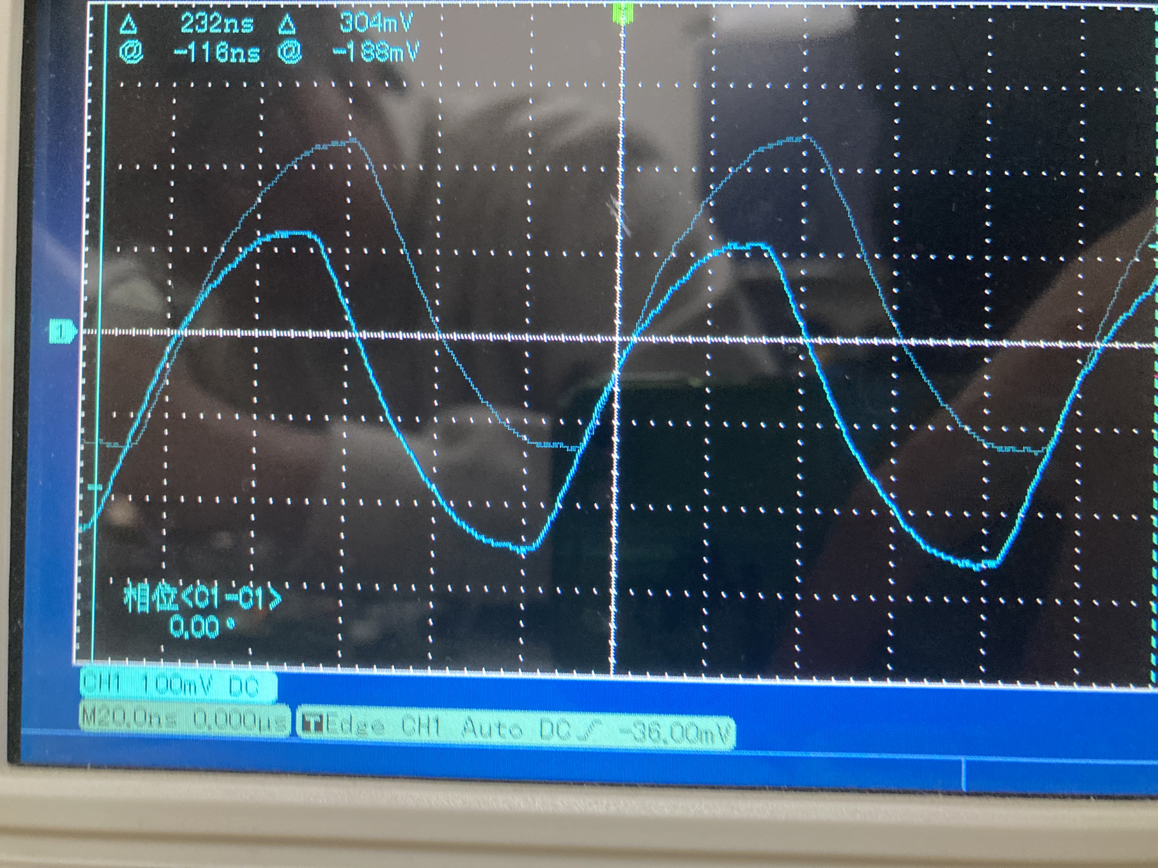
Summary
Peak-Peak Amp ——368.0mV
Frequency —— 10.02MHz
Pin 6 - Output
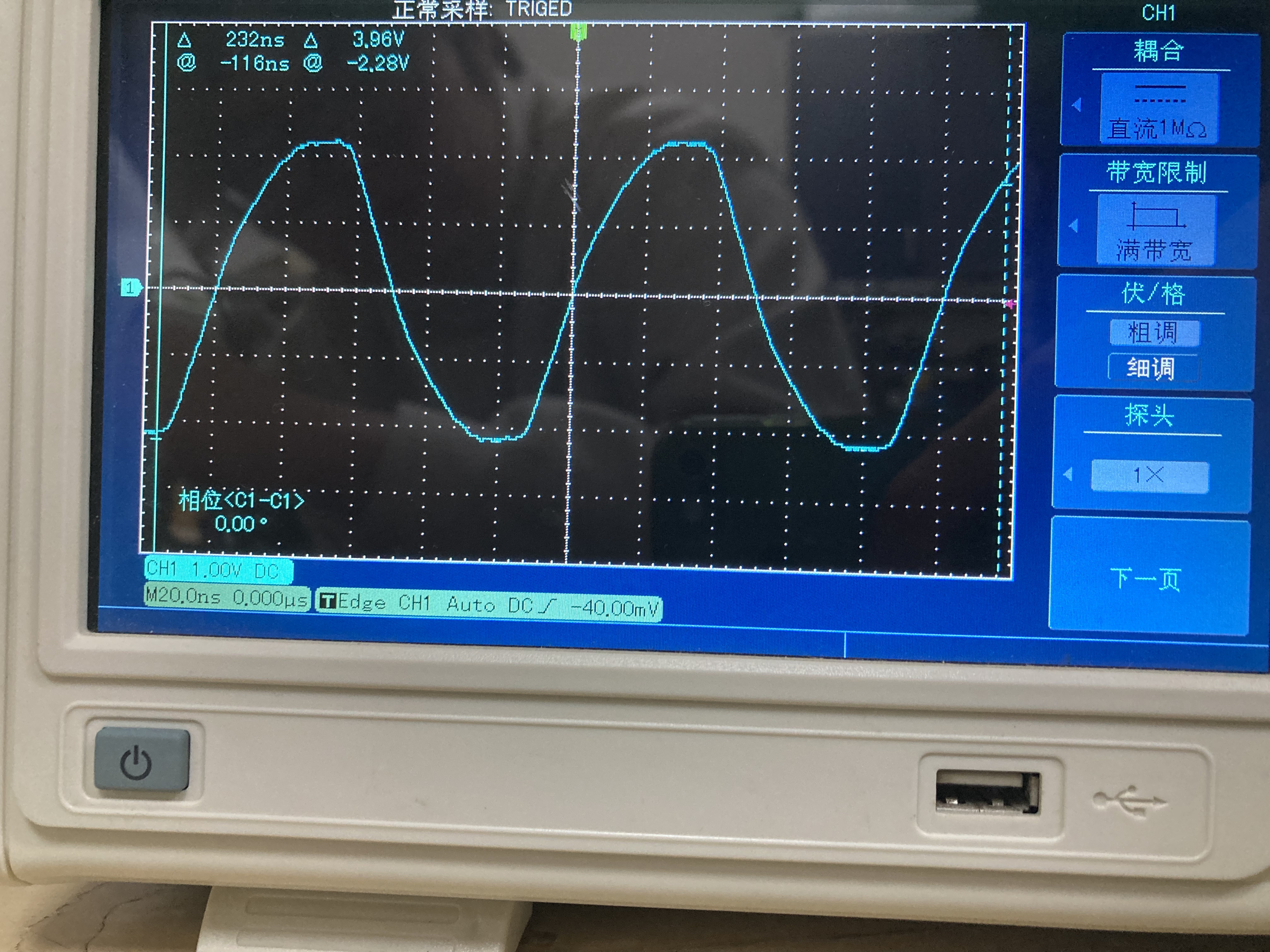
Summary
Peak-Peak Amp ——4.44V
Frequency —— 10.03MHz