Actual Signals which find use in UWB systems
- Gaussian-derived pulses
- Edge-derived pulses
- Sinc pulses
- Truncated sine pulses
- Chirp signals (frequency sweep)
Gaussian-derived pulses
Time-domain function:
Frequency-domain function:
Methods of generating UWB signals
There are two methods to generate UWB signals.
- Radio Frequency (RF)/ microwave analogue techniques
- Digital synthesis methods such as direct digital synthesis (DSS).
RF, micro analogue techniques
Modern analogue techniques make use of solid-state devices such as diodes and transistors.
Diodes:
- Step recovery diodes (SRDs)
- Tunnel diodes
- Schottky diodes
DDS
Specific Example of using DDS to generate UWB signal

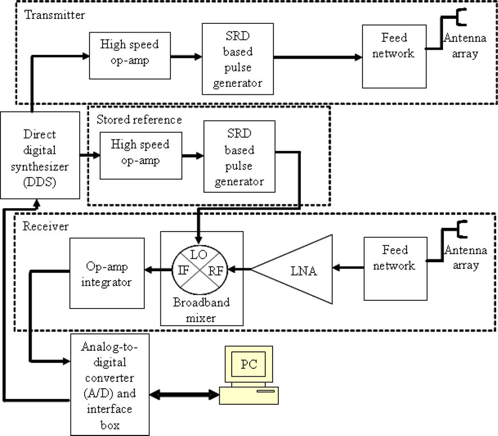
In this article, Circularly Polarized Ultra-Wideband Radar System for Vital Signs Monitoring, it uses AD9959 DDS to control UWB pulse repetition frequency (PRF). This DDS has the capability to generate sinusoids up to 250MHz at 0.1-Hz frequency tuning resolution. The DDS has four channels, one for transmitting pulse, one for storing reference pulse from receiver.
The outputs from the DDS, the sinusoids will be amplified by op-amps(Texas Instruments Incorporated OPA699, in this article). After amplifying, the signal will be fed to step recovery diode(SRD).
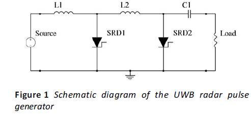
The cascaded shunt mode SRD with decreasing lifetime method of pulse generation produces high amplitude pulses of 3 at low PRFs (megahertz range), thus the pulse generator can directly drive the antenna subsystem saving the need for expensive broadband power amplifiers
This method is introduced in other article, Chan, K. K. M., et al. “Efficient Passive Low-Rate Pulse Generator for Ultra-Wideband Radar.” IET Microwaves, Antennas & Propagation, vol. 4, no. 12, 2010, p. 2196. DOI.org (Crossref), https://doi.org/10.1049/iet-map.2010.0030.. It says that, a commonly used scheme for UWB pulse generation is the shunt-mode SRD impulse generator.

The source, 50 waveform generator, generates CWs with amplitudes greater than turn-on voltages of SRD1 and SRD2. L1 and SRD1 form the first stage of the shunt-mode harmonic generator, whereas L2 and SRD2 form the second stage. First stage is cascaded with second stage in series configuration.
For different UWB applications, such as 5GHz, 10GHz, …, we can calculated components’ parameters to design. The key formulas are,
After SRDs based pulse generator, the CWs will transform to UWB pulse. The last step is eject the UWB signal by feed network and antenna.